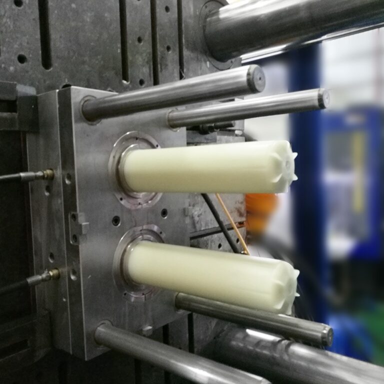
Description of basic elements of injection molding
1. Pressure
The action pressure provided by the pressure system (oil pump) of the injection molding machine or the driver’s motor is mainly used in various action programs such as the injection device, the Plastic melting device, the mold opening and locking device, the ejection device, the shooting table device, and the core pulling device. After the control panel of the injection molding machine inputs relevant parameters, the processor converts them into the signals of each program action, so as to control the pressure required for the execution of each action program.
The principle of pressure setting is to overcome the corresponding force of the action resistance, but adjust the parameter value accordingly to match the action speed.

2. Speed
The movement speed (flow of system hydraulic oil) required to complete each action procedure is matched with the above pressure. The basic classification of speed is: slow flow 0.1-10, slow flow 11-30, medium speed 31-60, and high speed 61-99.
1 The control of Plastic injection speed should be applied to different product structures and materials to set the size values. It is easy to confuse the public and the public here if we do not distinguish (engineering/general plastics, crystalline/amorphous plastics, high-temperature/low-temperature plastics, soft Plastic/hard Plastic plastics). It is easy to understand that the Plastic injection speed is a relatively difficult process element to control in injection molding, Unlike other process elements, there are standard data for reference (detailed introduction will be made later).
The numerical setting of Plastic injection speed mainly follows the following points:
According to the fluidity of materials; For example, PP, LDPE, TPE, TPR, TPU, PVC and other soft plastics have good fluidity, and their cavity resistance is small when filling. Generally, lower injection speed can be used to fill the cavity. For example, ABS, HIPS, GPPS, POM, PMMA, PC+ABS, Q Plastic, K Plastic, HDPE, and other commonly used medium viscosity plastics have a slightly poor fluidity. When the requirements for product appearance glossiness are not high or the product meat thickness is moderate (the product wall thickness or bone thickness is more than 1.5 mm), the Plastic injection speed can be used to fill, otherwise, the filling speed should be appropriately increased according to the product structure or appearance requirements.
For example, PC, PA+GF, PBT+GF, LCP and other engineering plastics have poor fluidity, so high-speed Plastic injection is generally required during filling, especially for materials that increase GF (glass fiber). If the Plastic injection speed is too slow, the floating fiber (surface craze) on the product surface will be serious.
3. Control of Plastic melting speed;
This parameter is one of the most easily ignored processes in daily work. Because most colleagues think that this process has little impact on molding, products can be made if the parameters are adjusted freely. However, in injection molding, the Plastic melting parameter is as important as the Plastic injection speed. The Plastic melting speed can directly affect the melt mixing effect, molding cycle and other important links.
4. Control of mold opening and locking speed;
Different parameters are mainly set for different die structures. For example, the production efficiency can be effectively improved by adjusting the high-speed clamping of the two plate plane die before starting the clamping low pressure and adjusting the high-speed clamping after the product is separated from the mold cavity. However, when adjusting the speed of mold opening and locking for the mold with row position, the switch between fast and slow speed of mold opening and locking shall be determined according to the height and structure of row position. Due to the complex structure of the special mold structure and core pulling mold, the following chapters will give a good explanation.
5. Control of ejector speed;
It mainly depends on the demoulding condition of the product. In principle, it should be as fast as possible on the premise of ensuring that the top white, top height or deformation of the product does not occur. Otherwise, it is necessary to adjust the parameters appropriately according to the actual situation, of course; In general, it is better to adjust the jacking speed for the first time at medium and low speeds (15% – 35%), which can effectively prolong the service life of the thimble and the thimble cylinder.
6. Location
Switching point between fast and slow speed, high and low voltage of each action
6.1 Control of Plastic injection position;
During the debugging of injection molding parameters, the injection position needs to be adjusted according to the unit weight and structure of the product. In consideration of the unit weight of the product to adjust the position, that is, how much Plastic the product needs,
For example, the unit weight of a product is about 50G, and it is produced by 90T injection molding machine. The theoretical Plastic injection amount of the model is 120G, the melt stroke is 130MM, and the melt weight per MM is about 120G ÷ the melt stroke is 130MM=0.92G, that is, the Plastic injection distance of the product is 50 × 0.92=46MM position. If the melt Plastic termination position is set at 60MM, the product quality is basically OK when the Plastic injection reaches 14MM.
(Of course, the above is an empirical statement. There is a little deviation. Because the screw compression ratio calculation formula in the book is not followed, it is too complicated. I believe most of my colleagues can not count it.) As for how to control the undesirable phenomena of various molded products with the injection position.
6.2. Control of Plastic melting position;
It is generally understood that the Plastic injection distance should be set according to the required Plastic injection amount of the molded products. Most colleagues ignore the three section switching positions of the Plastic and only pay attention to the final position of the Plastic, of course; For molded products with ordinary difficulties, it is not necessary to switch between fast and slow speed or high and low back pressure when adjusting the position of Plastic melting. The required product quality can still be achieved. However, the product quality can be better controlled by properly switching the speed of Plastic melting and the position of back pressure when producing masterbatch and plastics with high heat sensitivity.
6.3. Position control of mold opening and locking;
It is mainly used to set the switching point according to the needs of mold opening and locking speed
6.3.1 In general, the switching point of the mold opening speed is that the molded product is slow before it leaves the mold cavity (about 5-15 mm), and fast after it, which can effectively shorten the time required for mold opening, and finally turn slowly (that is, the mold opening buffer position, generally 20-40 mm away from the required mold opening end position is better to start the cutting, (the end position depends on the product structure and whether a manipulator is used), It can effectively prolong the service life of the hinge of the injection molding machine and stabilize the opening action.
The opening speed of some special mold structural factors, such as three plate mold or core pulling mold, shall be determined according to the actual situation. For example, since the product cavity of the three plate mold is on the middle plate, the first action is on the nozzle plate when opening the mold, and the nozzle runner shall be separated from the product before the male and female molds are separated. Therefore, 1-2 switching points shall be added at the opening position, which is medium speed – slow speed – high speed – slow speed, For machines with large tonnage, several more switching points can be added as required. In short, the quality of molded products is not affected during the mold opening process and the action process is stable.
6.3.2 The setting of clamping position mainly depends on the mold structure. For example, the plane mold structure (that is, the parting surfaces of the front and rear molds are flat, without sliding block/core pulling, and without penetration structure) can directly use four sections of positions to switch the clamping speed. The switching principle of its position is: the quick stroke of clamping is about 70% of the opening stroke, (The quick termination position of the three plate mold depends on the structure size of the mold), which is mainly used to shorten the mold clamping cycle. Turn back to medium speed, which acts as the deceleration buffer of high-speed mode locking (because it will switch to low-voltage protection function after medium speed)
The termination position of the mode locking medium speed is very important, which determines the starting position of the mode locking low-voltage protection. Some senior staff members are very vague about the mode locking low-voltage, and think that the mode can be locked at any setting, but in fact it is not. If the clamping low pressure is set improperly, its protection function will be completely lost, which is fatal to the fully automatic production mold.
6.3.4. Control of ejector pin position;
Theoretically, the ejection length of the ejector pin is twice the height of the mold cavity (i.e. the mold core) behind the mold. However, in actual operation, it is unnecessary to set the position completely according to this method, which is mainly for the convenience of taking out the product. However, when the ejector pin position is adjusted for the first time, it needs to be gradually lengthened. First, it needs to eject 50% of the ejector pin stroke of the mold, and then it depends on the product taking out condition during the production process.
7. Temperature
Necessary conditions for plastic melting and mold heating
7.1 Control of material pipe temperature;
Generally, there are relatively standard molding temperatures for plastics with different properties, such as ABS=(high impact resistance 230-260, low impact resistance 190-230), SAN=180-220, HIPS=180-220, POM=170-200, PC=240-300, ABS/PC=230-260, PMMA=200-230, PVC=(high density 160-200, low density 140-180), PP=180-230, PE=(high density 240-300, low density 180-230);
TPE=(high density: 170-200, low density: 140-180), TPR=(high density: 170-200, low density: 140-180), TPU=(high density: 160-200, low density: 120-160), PA=230-270, PA+fiber=250-300, PBT=200-240, PBT+fiber=240-280. In addition, the molding temperature of any flame retardant (i.e. fire retardant) added shall be 20-30 ℃ lower than that of ordinary materials. The specific use temperature depends on the production situation, because the molding temperature directly affects the fluidity, viscosity, mold temperature, color, shrinkage, product deformation, etc.
7.2 Mold temperature control;
The mold temperature is mainly determined for different plastic fluidity. It can be simply understood that it is the key process to overcome the poor fluidity. For example, PC material and PA+fiber material have poor fluidity, and their flow resistance in the filling process is large, so they need a faster injection speed to fill.
In addition, when producing PC transparent rubber parts, higher mold temperature is required to improve the bad problems such as air lines, rainbow prints and internal bubbles on the product surface. If the mold temperature is lower during the production of fiber adding materials, silver lines (floating fibers) will appear on the surface.
In general, the mold temperature can be adjusted by referring to the following data:
ABS=30-50 (products with high surface quality requirements or requiring deformation control can be increased to 60-110 degrees) PC=50-80 (products with high surface quality requirements or thin wall can be increased to 85-140 degrees) HIPS=30-50 (transparent PS and products with high surface quality requirements can be increased to 60-80 degrees)
PMMA=60-80 (thin-walled products and products with high surface quality requirements can be increased to 80-120 degrees) PP=10-50, PE=10-50 (mold temperature can be appropriately increased for high-density or thin-walled products) Rubber (TPE, TPR, TPU)=10-50,
PA, PBT=30-60 (high surface quality requirements and glass fiber added materials can be increased to 70-100)
8. Time
Time of each action
8.1. Control of filling time;
Including Plastic injection time and pressure holding time
8.1.1. Plastic injection time:
Generally, the shorter the required product is, the better if the quality is qualified. Because the injection time directly affects the internal stress and production cycle of the product, in principle, the thinner the product’s Plastic level is, the shorter the injection time will be. On the contrary, for thick walled products, the injection time should be extended as appropriate to control their shrinkage.
In addition, the use of products with multiple sections and large switching range of fast and slow speeds requires a longer injection time. The injection time should also be set according to the product volume (the larger the product is, the longer the injection time is required). Here, the properties of plastics for production should also be considered. For example, when the product wall thickness is 2.0MM, the injection speed is moderate, and the tube temperature is moderate, the flow rate is about 65mm/s in the longitudinal direction (different mold structures or processes have different flows).
8.1.2. Pressure holding time:
In principle, the pressure holding time mainly controls the surface shrinkage of the product and the structure size of the product, but it can also be used to adjust the deformation of the product after fully mastering the control method of the pressure holding time (therefore, the adjustment process is a precision adjustment process, and its adjustment method will be described in detail in the following chapters).
Here is a brief introduction to the use of pressure maintaining to control the shrinkage of the product. Generally, the use of pressure maintaining to control the shrinkage of the product depends on the shrinkage position of the product. Not all shrinkage can be solved by pressure maintaining. For example, the shrinkage position is at the end of the melt filling. If pressure maintaining is used to control the shrinkage, the stress near the nozzle position will be too large, resulting in white top, die sticking, or product warping and deformation.
8.1.3. Ejector extension Time;
It mainly controls the residence time of the ejector pin when ejecting, so as to facilitate the manipulator to pick up the products.
8.1.4. Core pulling time;
Control the action time of the core pulling device of the injection molding machine (mainly used to control the action travel by time). If the core pulling device is controlled by an inductive switch, the core pulling time can be set.